Voltage Regulators🔗
Beginner
This article is in the Power topic. It builds on Ohm's Law and Power, Diodes and LEDs, and Transistors, and uses the capacitors and inductors from Circuit Foundations. No other prior knowledge required.
Two parts can each turn a 12 V supply into a steady 5 V for a load that draws 3 A. One of them, a linear regulator, takes 36 W from the supply to do it and turns 21 W of that into heat. The other, a switching regulator, takes under 19 W and wastes less than 4. Both deliver exactly the same 15 W to the load.
Two ideas explain the difference:
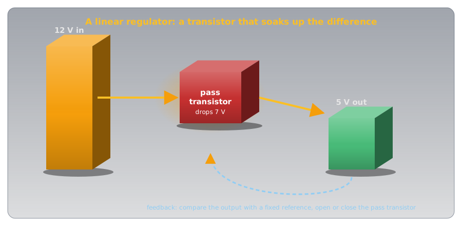
- A linear regulator is a transistor that soaks up the difference. It sits between the supply and the load, constantly adjusting itself so the load sees exactly the right voltage, and every volt it removes becomes heat. Its input current always equals its output current.
- A switching regulator chops the supply on and off and smooths the result. A switch that's fully on or fully off wastes almost nothing, so the energy goes to the load instead of into heat, and the input current can be smaller than the output current.
The numbers in the hook come out of those two ideas, with real datasheets, in the second half.
Why Regulate at All?🔗
Batteries sag as they discharge (Cells and Batteries explains why), rectified AC arrives in humps, and every supply's voltage dips when the load draws more. Many circuits don't tolerate that: a microcontroller wants 5 V or 3.3 V within a few percent, and the analog readings on Reading an Analog Sensor are only as accurate as the voltage they're measured against.
A voltage regulator turns a varying, too-high input into a fixed output that stays put while the input and the load change. The simplest one is already on this site: Diodes and LEDs showed a Zener diode holding 5.1 V. It works, but only for light loads, and it wastes current even with no load at all. Real regulators build on the same idea.
Idea One: A Transistor That Soaks Up the Difference🔗
A linear regulator puts a transistor, the pass transistor, in series between the input and the output. A small circuit inside compares the output with a fixed internal reference voltage and adjusts the transistor continuously: if the output drifts high, it turns the transistor down; if it sags, it turns it up. The transistor behaves like a resistor that keeps resetting itself to whatever value leaves exactly 5 V at the output.
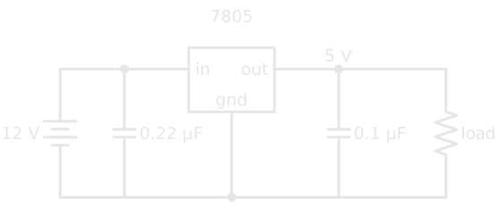
The classic part is the 7805, a three-terminal regulator (input, ground, output) that TI's LM340 / LM7805 datasheet rates for up to 1.5 A at 5 V. It needs almost nothing around it: the datasheet's measurements use a 0.22 µF capacitor at the input and 0.1 µF at the output.
Every Volt Removed Becomes Heat🔗
The pass transistor carries the full load current and has the difference between input and output across it. By Ohm's Law and Power, it dissipates
The input current is the same as the output current (plus a few milliamps the regulator uses itself: about 6 mA for the 7805), so the efficiency is simply the output voltage over the input voltage. From 12 V to 5 V, that's 5 ÷ 12, about 42%. Whatever the load, more than half the energy becomes heat.
That heat has to go somewhere, and the datasheet says how fast it can. A 7805 in the common TO-220 package (Package Types shows one) has a junction-to-ambient thermal resistance of 23.9 °C per watt with no heat sink: every watt raises the chip 23.9 °C above the room. Its maximum operating temperature is 125 °C, and above 150 °C it shuts itself down to survive.
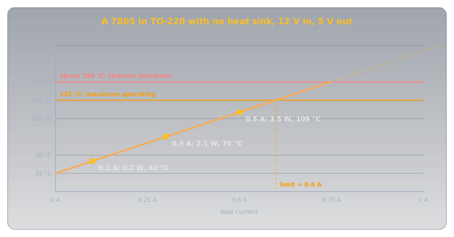
The datasheet gives the limit as Pmax = (TJ max − Tambient) ÷ θJA. In a 25 °C room that's (125 − 25) ÷ 23.9 ≈ 4.2 W, or about 0.6 A at a 7 V drop. Beyond that the regulator needs a heat sink: a finned metal block bolted to the TO-220's tab that gives the heat a larger surface to leave through. For 1 A (7 W) the whole path from chip to air would need to be under (125 − 25) ÷ 7 ≈ 14 °C/W.
That's why, in a mains power supply, the regulator is the stage that usually wears a heat sink.
Definition: Thermal Resistance
How many degrees a part's temperature rises above its surroundings for each watt it dissipates, in °C/W. Lower is better. A heat sink lowers it by giving the heat more surface area to escape from.
Dropout: the Headroom a Regulator Needs🔗
A linear regulator can only remove voltage, and the pass transistor needs some voltage across it to work at all. The minimum is the dropout voltage: 2 V at 1 A for the 7805, so it needs at least 7 V in to deliver 5 V. Below that, the output simply follows the input down.
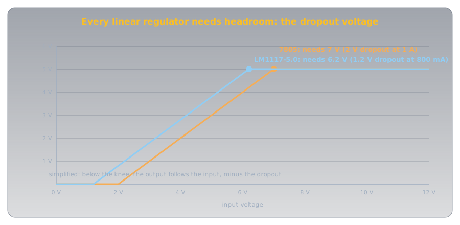
A low-dropout regulator (LDO) is built to need less. TI's LM1117 drops out at 1.2 V at 800 mA, which is what lets a 5 V USB supply feed a 3.3 V circuit through a linear regulator: 5 − 3.3 = 1.7 V of headroom, comfortably above 1.2 V.
Dropout matters most on batteries: a regulator with a small dropout keeps working further into the battery's discharge. And a low input voltage is good for efficiency too, since less headroom means less heat.
Adjustable Regulators🔗
Fixed regulators come in common voltages (the 78xx family includes 5, 12, and 15 V parts). For anything else, an adjustable regulator such as the LM317 sets its output with two resistors: Voltage Dividers works through its formula. Its heat follows exactly the same rule as the 7805's.
Idea Two: Switch It, Then Smooth It🔗
A transistor wastes almost no power in two states: fully off, when no current flows through it, and fully on, when almost no voltage is across it. Transistors showed that the waste happens in between, and a linear regulator lives permanently in between. A switching regulator never does. It flicks a transistor fully on and fully off many thousands of times a second, and smooths the chopped result back into steady DC.
The step-down version is called a buck converter. Switched on 42% of the time, 12 V averages 12 × 0.42 = 5 V:
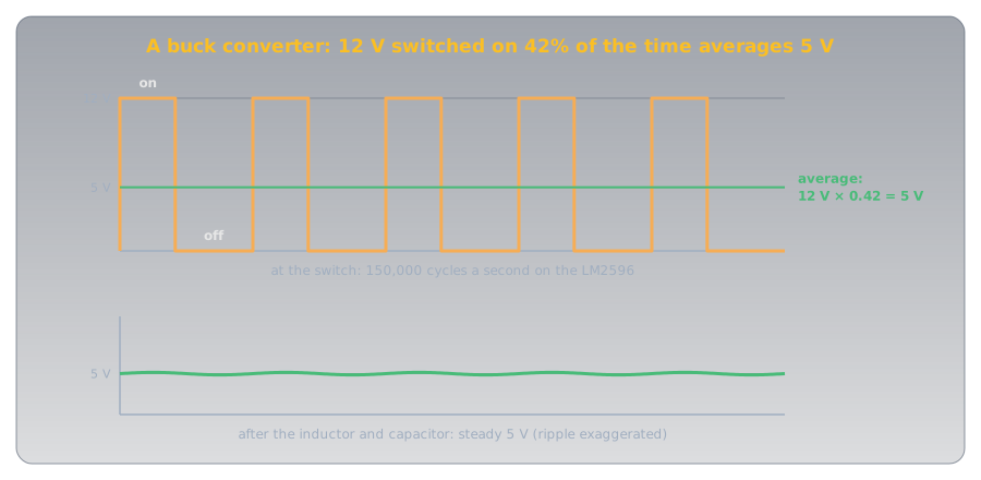
The smoothing is done by an inductor and a capacitor, the two parts that store energy:
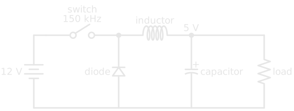
- Switch on: current flows from the input through the inductor to the load, and builds up in the inductor's magnetic field.
- Switch off: an inductor resists any change in its current (Inductors), so the current keeps flowing, now drawn up through the diode from ground. The energy stored in the field feeds the load until the switch comes back on.
- The capacitor irons out what's left, so the load sees a steady 5 V with a small ripple.
The Hook, Solved🔗
TI's LM2596 is a common buck regulator chip, switching at 150 kHz and rated for 3 A. Its datasheet gives the 5 V version an efficiency of 80% at 12 V in and 3 A out. Compare it with a linear regulator doing the same job:
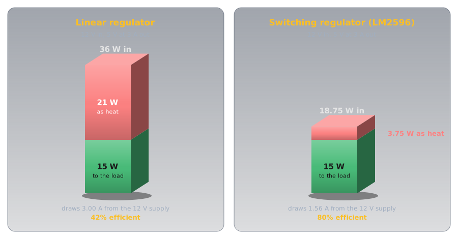
| Linear | Switching (LM2596) | |
|---|---|---|
| Power to the load | 15 W | 15 W |
| Power from the 12 V supply | 15 ÷ 0.42 = 36 W | 15 ÷ 0.80 = 18.75 W |
| Heat | 21 W | 3.75 W |
| Current from the supply | 3 A | 18.75 ÷ 12 ≈ 1.56 A |
A switcher's input current is smaller than its output current when stepping down, something no linear regulator can do: power in is roughly power out, so lower voltage at the output comes with higher current. (In practice the 7805 couldn't do this job at all: its 1.5 A rating is half of the 3 A needed.)
What Switching Costs🔗
Efficiency isn't free. A switching regulator needs more parts, and its fast edges make electrical noise: the 150 kHz switching and its harmonics can couple into nearby circuits and leak onto the supply wires. A linear regulator makes essentially none; the 7805 datasheet even specifies how well it removes ripple, 68 to 80 dB at 120 Hz, which turns 0.6 V of ripple into a fraction of a millivolt.
| Linear | Switching | |
|---|---|---|
| Efficiency | Vout ÷ Vin; poor for big drops | 73–90% for the LM2596's versions at full load |
| Heat | (Vin − Vout) × I | small |
| Size and weight | larger: heat sinks, big transformers | smaller and lighter |
| Electrical noise | very low | switching noise to filter |
| Parts count | three pins and two capacitors | controller, inductor, diode, capacitors |
| Can step up | no | yes (boost converters) |
So the choice follows the job. Battery-powered and portable equipment, phone chargers, and laptop supplies use switchers for their efficiency, size, and weight. Sensitive analog circuits and radio receivers, where switching noise would be heard, are where linear supplies keep their place. Switchers can also step voltage up: the camera flash in Capacitors charges its 300 V capacitor from two AA cells with a boost converter.
Putting It Together: a Linear Power Supply🔗
A power supply that runs from the wall chains together parts from all over this site. Each stage hands the next a cleaner, steadier voltage:
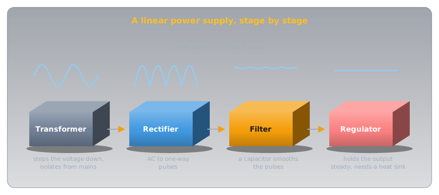
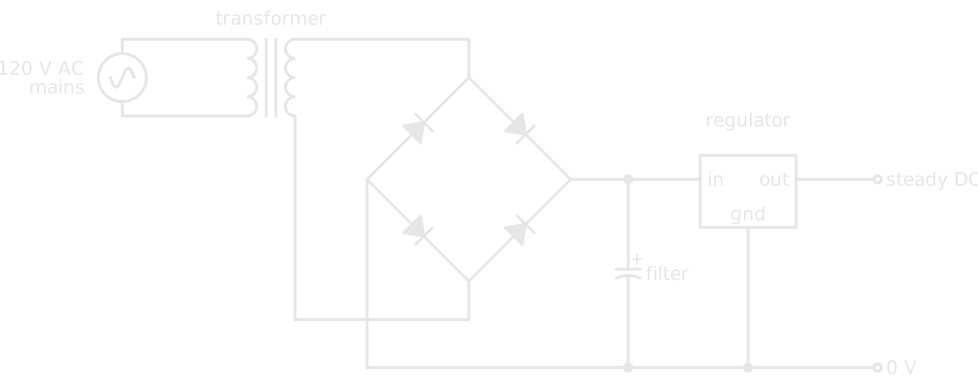
- The transformer steps the 120 V mains down to a lower AC voltage and, because its two windings aren't connected, isolates everything after it from the mains (Magnetism and Electromagnetism explains how).
- The rectifier turns that AC into one-way pulses. A bridge of four diodes gives about 15.5 V peaks from 12 V AC (Diodes and LEDs).
- The filter, a large capacitor, fills at each peak and feeds the load between them. Capacitors works the numbers: 2,200 µF sags only about 0.6 V between peaks.
- The regulator removes what's left of the ripple and holds the output constant as the load changes. A
7805here sees about 15.5 V in, well above its 7 V minimum even at the bottom of the ripple, and at 150 mA dissipates (15.5 − 5) × 0.15 ≈ 1.6 W: within its limit, but warm enough that many designs add a small heat sink anyway.
Bench and station supplies add protection after the regulator. An overvoltage circuit watches the regulator's output, where a failure would reach the equipment, and if the voltage climbs too high a crowbar circuit shorts the output deliberately, blowing the fuse or tripping the supply's current limit before the overvoltage can do damage (Crowbar on Wikipedia).
Safety🔗
The low-voltage side of a supply is safe to experiment with; the parts that make it are the dangerous ones.
Mains Supplies Hold Lethal Voltages
The primary side of any mains power supply is at mains voltage, and the filter capacitors on either side can stay charged after it's unplugged (Capacitors). Don't open a mains-powered supply unless you've been trained to; build regulator circuits from batteries, a USB supply, or a commercial low-voltage adapter, so the mains stays inside a sealed, certified box.
Regulators Get Hot
A linear regulator dropping a few volts at a few hundred milliamps is hot enough to burn a fingertip, and its tab is connected to one of its pins, so bolting two to the same heat sink without insulating washers can short them together. Check the datasheet's thermal numbers before building, not after something smells hot.
Practice🔗
1. How Much Heat?
A 7805 supplies 200 mA at 5 V from a 9 V battery. How much power does it turn into heat, and what's its efficiency?
Solution
Efficiency is 5 ÷ 9 ≈ 56%. Lowering the input voltage, as long as it stays above the 7 V minimum, is the cheapest way to make a linear regulator run cooler.
2. Does It Need a Heat Sink?
A 7805 in TO-220 (23.9 °C/W, 125 °C maximum) drops 12 V to 5 V for a 400 mA load in a 30 °C room. Is it within its limit without a heat sink?
Solution
Power: (12 − 5) × 0.4 = 2.8 W. Temperature rise: 2.8 × 23.9 ≈ 67 °C, so the chip reaches about 30 + 67 = 97 °C. That's within the 125 °C limit, but hot; a small heat sink would give it margin.
3. Will It Regulate?
A 7805 (2 V dropout) is powered from four AA cells in series, which start at about 6 V. Will it hold 5 V? What about an LDO with 0.3 V of dropout?
Solution
The 7805 won't: it needs at least 7 V, so from 6 V its output follows the input down to about 4 V. An LDO with 0.3 V of dropout needs only 5.3 V, so it regulates until the cells sag below that.
4. Input Current
A buck converter delivers 5 V at 2 A with 85% efficiency, from a 12 V supply. How much current does it draw? How much would a linear regulator draw?
Solution
Output power is 10 W, so the input is 10 ÷ 0.85 ≈ 11.8 W, and 11.8 ÷ 12 ≈ 0.98 A. A linear regulator draws the full 2 A, because its input current always equals its output current.
5. Name the Stage
In a linear power supply, which stage converts AC to pulsating DC, which smooths it, which isolates the circuit from the mains, and which usually needs a heat sink?
Solution
The rectifier converts AC to pulsating DC. The filter (capacitor) smooths it. The transformer isolates it from the mains and sets the voltage. The regulator usually needs the heat sink, because it turns the excess voltage times the load current into heat.
6. Linear or Switching?
For each, which would you choose: a battery-powered sensor that must run for months; a supply for a sensitive radio receiver; a 5 V, 3 A supply from 24 V?
Solution
Switching for the battery sensor, since efficiency is battery life. Linear for the receiver, since it makes no switching noise to be heard. Switching for 24 V to 5 V at 3 A: a linear regulator would turn (24 − 5) × 3 = 57 W into heat.
Quick Recap🔗
-
A regulator holds the output
A fixed output from a varying input, steady as the load changes.
-
Linear: the transistor soaks up the difference
Heat = (Vin − Vout) × I. Input current equals output current. Efficiency ≈ Vout ÷ Vin.
-
Thermal resistance sets the limit
°C per watt. A TO-220
7805from 12 V to 5 V reaches its limit near 0.6 A without a heat sink. -
Dropout is the minimum headroom
2 V for a
7805, about 1.2 V for the LM1117 LDO. Below it, no regulation. -
Switching: chop and smooth
A transistor fully on or fully off wastes little. An inductor and capacitor smooth the result.
-
Switchers trade noise for efficiency
Smaller, lighter, cooler, and able to step up; but they make switching noise. Linear supplies stay quiet.
-
The supply chain
Transformer (step down and isolate), rectifier (AC to pulses), filter (smooth), regulator (hold steady, heat sink).
-
Protection after the regulator
Overvoltage is sensed at the regulator's output; a crowbar shorts it and blows the fuse.
What's Next🔗
A regulator is only as good as the supply behind it. On the bench, an adjustable one with a current limit is the safest way to power a new circuit: Bench Power Supplies covers it. Cells and Batteries covers the portable end: how cells sag, and why internal resistance decides how much current they can deliver. On the mains side, AC vs DC explains the waveform every power supply starts from.
Further Reading🔗
Datasheets
- Texas Instruments LM340 / LM7805 (PDF) — the fixed 5 V regulator: dropout, thermal resistance, thermal shutdown, and ripple rejection
- Texas Instruments LM1117 (PDF) — an 800 mA low-dropout regulator
- Texas Instruments LM2596 (PDF) — a 3 A, 150 kHz buck regulator and its efficiency
Deep Dives
- Voltage Regulator — Wikipedia — linear and switching designs and their history
- Buck Converter — Wikipedia — the switching cycle in detail
- Crowbar (circuit) — Wikipedia — overvoltage protection by deliberate short circuit
Related Articles
- Diodes and LEDs — rectifiers and the Zener reference
- Capacitors — smoothing, and the energy a filter capacitor holds
- Inductors — the energy store at the heart of a switching regulator
- Package Types — the TO-220 package and its heat-sink tab