Digital Pins🔗
Beginner
This article is in the Microcontrollers topic. It builds on Voltage, Current, and Ohm's Law and Power; read those first if voltage, current, and the job of a resistor are new to you. If you've never seen an Arduino, start with What Is an Arduino?, which covers the board and how to read its code.
Look at the light switch on your wall. It's up or it's down. The light is on or it's off. There's no "half-on": the switch commits to one of two states and stays there until you move it.
A digital pin is a microcontroller's version of that switch. It's a single metal connection along the edge of the board that is only ever in one of two states: fully on or fully off. A microcontroller like an Arduino Uno has a row of them, and your program decides, many times a second, which are on and which are off, or listens to whether the outside world is pushing them on or off.
That's the whole idea behind making hardware do something. This article covers what the two states actually are, the two jobs a pin can take, and why a pin almost never connects to anything without a resistor in the way.
On, Off, and Nothing in Between🔗
"Digital" means two states, and only two. Engineers give them names:
- HIGH: the pin is at the supply voltage. On an Arduino Uno that's 5V.
- LOW: the pin is at 0V, the same as ground.
A program only ever sees those two values, and that restriction is what makes digital reliable. When the Uno reads a pin, its chip treats anything above 3V as HIGH and anything below 1.5V as LOW (the ATmega328P datasheet's thresholds, 60% and 30% of the 5V supply). A signal that sags from 5V to 4.6V, or picks up a few hundred millivolts of noise, still reads exactly the same. The band between 1.5V and 3V is the one place a reading isn't guaranteed, and a well-designed circuit never leaves a pin sitting there.
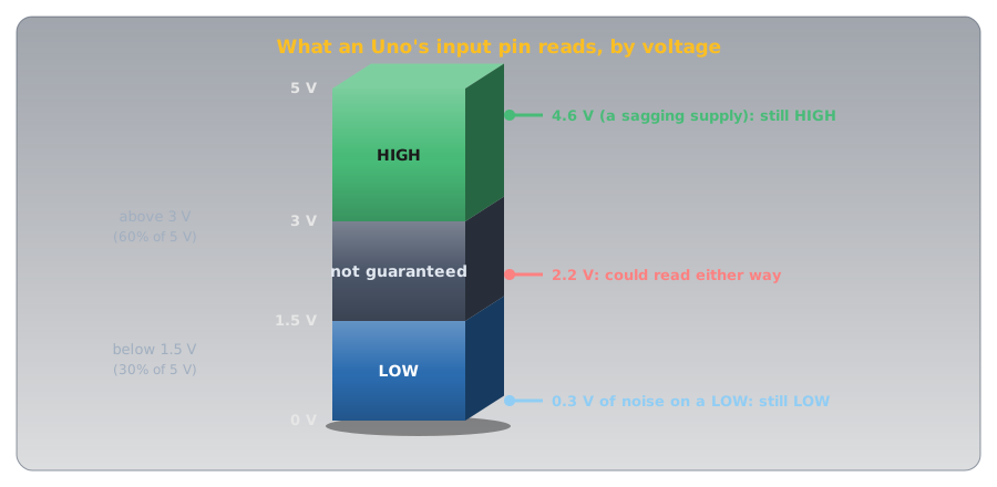
Your board may use 3.3V
The Uno's HIGH is 5V, but many modern boards, including the ESP32, the Raspberry Pi Pico, and the BBC micro:bit, use 3.3V. The idea is identical; only the voltage of HIGH changes. It matters the moment you connect two boards together, as the Safety section explains.
A Pin Has Two Possible Jobs🔗
Before a pin can do anything, you have to tell the microcontroller which of two jobs it should do:
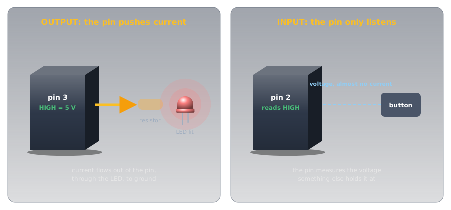
- OUTPUT — the pin provides voltage. The microcontroller drives it HIGH or LOW to switch something on or off, like an LED.
- INPUT — the pin senses voltage. The microcontroller reads whether something outside is holding the pin HIGH or LOW, like a button being pressed.
You set this once, when the program starts, with pinMode(). Get it backwards and nothing works: an output pin can't hear a button, and an input pin can't light an LED.
The code in this article is Arduino C/C++, the language an Arduino runs. If void, the curly braces, or setup()/loop() are unfamiliar, What Is an Arduino? walks through what each piece means before you hit it below. Once you're ready to actually run this code, arduino-cli covers compiling and uploading it.
Job One: Switching an LED On (OUTPUT)🔗
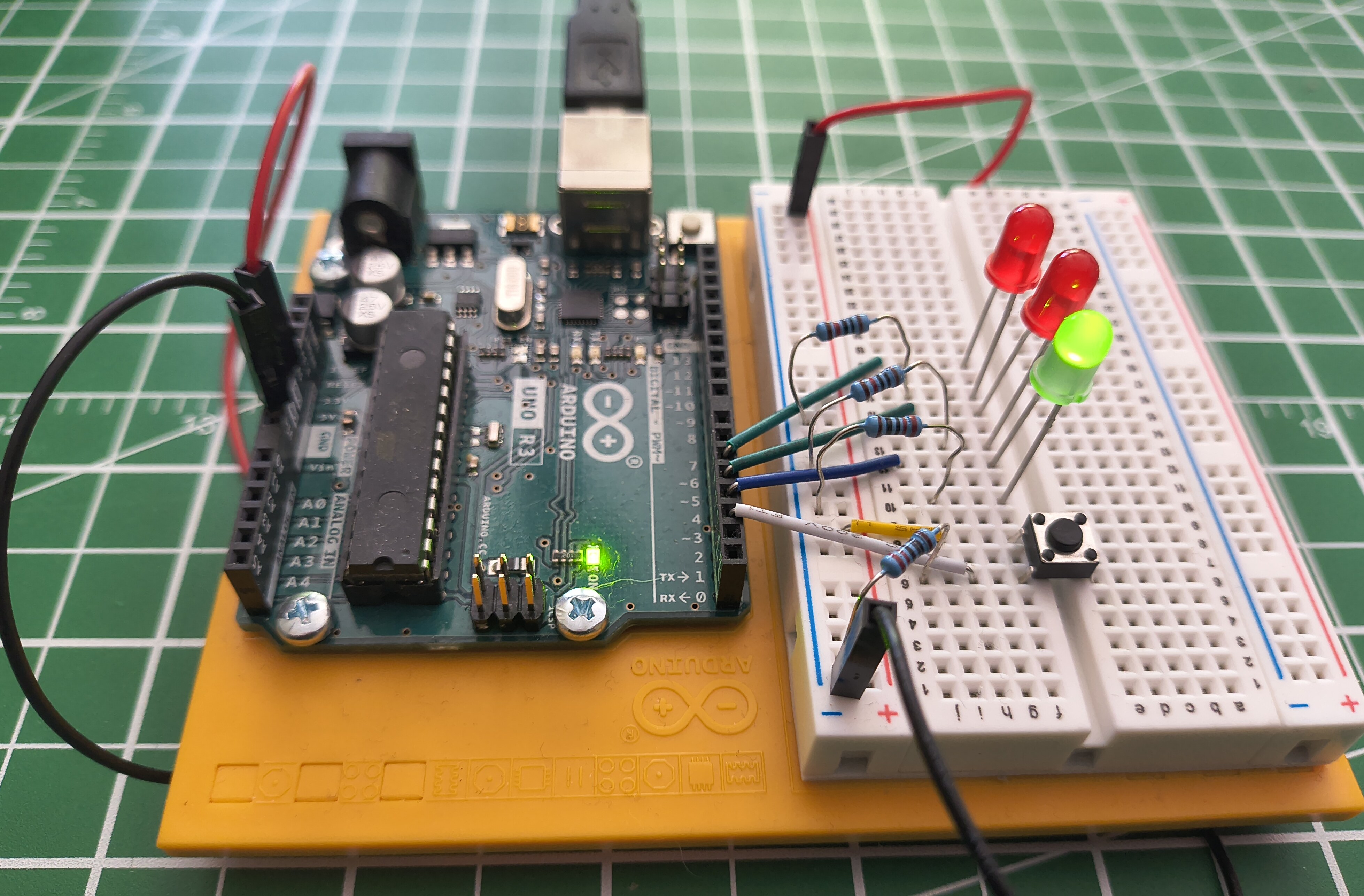
The simplest useful thing a pin can do is turn a light on. Here's the circuit on a breadboard, with an Arduino Uno on the left and three LEDs and a button on the right:
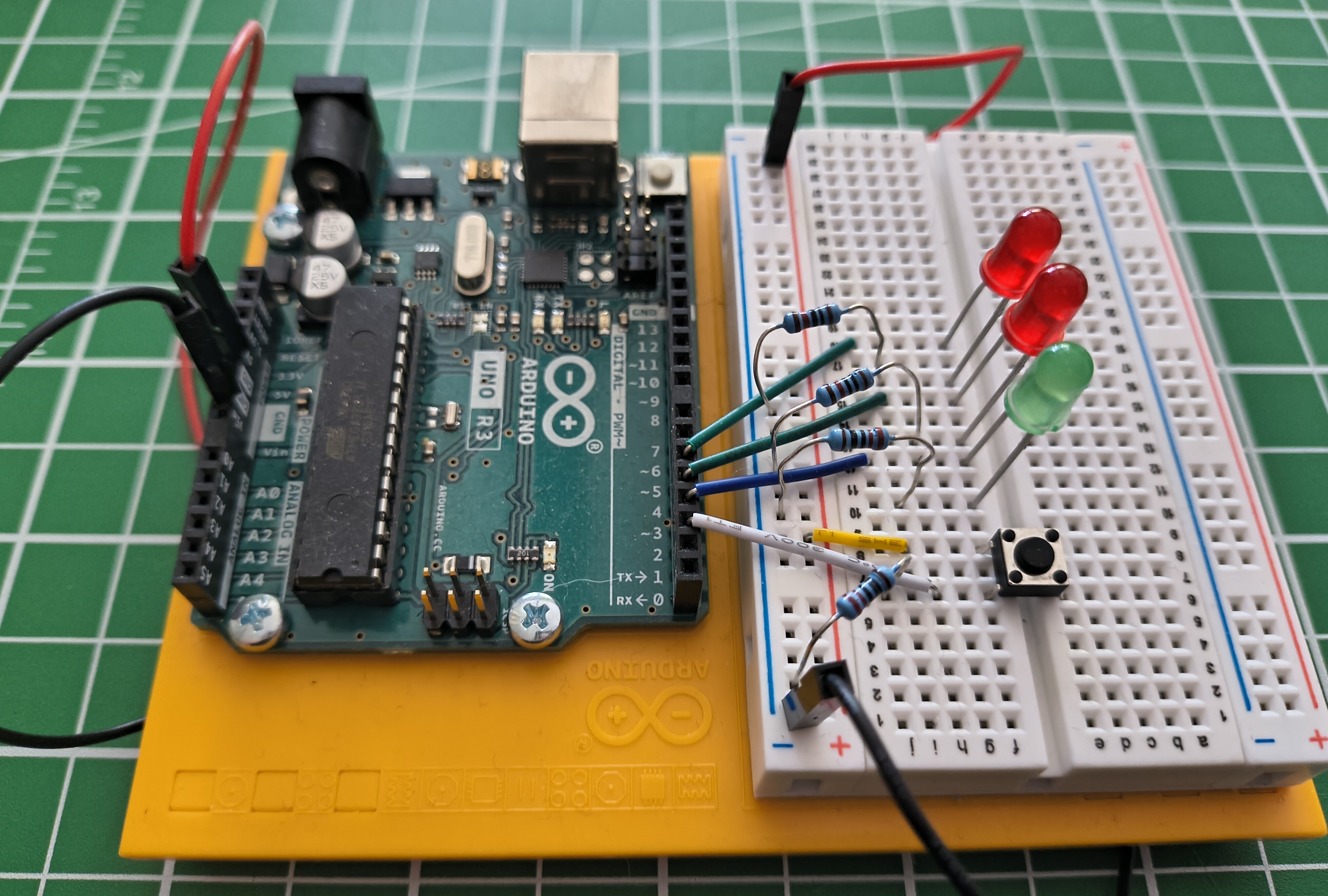
Follow just one LED. The pin connects to a resistor, the resistor to the LED, and the LED back to ground. Drawn as a schematic, the symbolic shorthand used in every tutorial and datasheet, that single path looks like this. (New to these symbols? How to Read a Schematic decodes each one.)
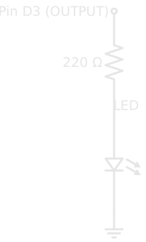
When the pin is HIGH, it sits at 5V while the far end of the LED sits at 0V (ground). That 5V difference pushes current through the LED, and it lights. When the pin goes LOW, both ends are at 0V, no current flows, and the LED goes dark.
In code, that's two steps: declare the pin an output once, then drive it.
| Light an LED on pin 3 | |
|---|---|
digitalWrite(3, HIGH) puts 5V on pin 3; digitalWrite(3, LOW) drops it to 0V. Alternate between them with a pause in between and the LED blinks: the first program nearly everyone writes on a microcontroller.
Why the Resistor Is Not Optional🔗
Notice the circuit never connects the LED straight to the pin. There's always a resistor first, and leaving it out is the most common way beginners destroy their first component.
An LED doesn't behave like a resistor. Below its forward voltage (about 2V for a red LED) it passes almost nothing; above it, the current climbs steeply with every extra fraction of a volt. Connected straight to 5V, it tries to draw far more current than it or the pin can survive. It may flare brightly and burn out, and it can damage the pin driving it. A resistor in series takes up the extra 3V and sets the current: Diodes and LEDs works out the value, and 220 Ω (about 14 mA) is the usual choice on 5V.
Always put a resistor in series with an LED
Connecting an LED directly to a pin with no resistor lets too much current flow. The LED can burn out instantly, and you can damage the microcontroller pin driving it. One resistor per LED, every time.
Job Two: Reading a Button (INPUT)🔗
Reading the world is trickier than driving it, and the reason surprises people: a digital input pin connected to nothing doesn't reliably read LOW. It floats.
An unconnected pin acts as a tiny antenna, picking up stray electrical noise from the air and from nearby wires. Read it and you'll get HIGH, then LOW, then HIGH again, with no pattern: it's drifting through the undefined band between the two thresholds. The pin isn't broken; there's simply nothing holding it at a definite voltage, so it drifts. A button alone doesn't fix it, because a button only connects the pin to anything while it's pressed.
The fix is a second resistor that holds the pin at a definite voltage whenever the button isn't. This circuit uses a pull-down resistor tying the pin to ground: the pin rests at a steady LOW and reads HIGH the instant the button connects it to 5V. With the pin pulled down, reading it is two lines:
| Read a button on pin 2 | |
|---|---|
digitalRead(2) returns the pin's current state, HIGH or LOW. With the pull-down in place, that's HIGH while you hold the button and LOW the moment you let go.
Giving an input a reliable resting state is its own skill (pull-down versus pull-up, choosing the value, and the pull-up built into the chip), so it has its own article: Pull-up and Pull-down Resistors.
Putting Both Jobs Together🔗
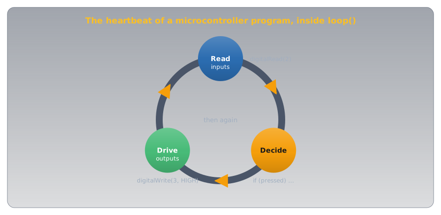
The photo at the top had three LEDs and a button, and now both halves make sense: the button is an input, the LEDs are outputs, and a program ties them together. Read the input, decide what to do, drive the outputs, thousands of times a second.
Power the same circuit up and the program's idle state shows: the green LED is lit, the reds are dark, waiting for the button.
That loop of reading inputs and driving outputs is the heartbeat of nearly every microcontroller program, from this button-and-LED circuit to a thermostat reading a sensor and switching a furnace.
The Same Idea on Every Board🔗
Once you understand digital pins on an Arduino, you understand them everywhere. Every microcontroller works this way: each digital pin can be set to INPUT or OUTPUT, reads or writes HIGH or LOW, and floats if you leave an input unconnected. An ESP32, a Raspberry Pi Pico, a micro:bit: same concept, same two jobs.
What changes from board to board is the detail, not the idea:
- The voltage of HIGH: 5V on an Uno, 3.3V on most newer boards.
- The pin numbers and how many there are.
- The exact code, though the shape is always the same: set the mode, then read or write.
Learn it once here, and every new board is just a new set of numbers on a pattern you already know.
Safety🔗
Nothing on a 5V Arduino can hurt you, but two mistakes destroy pins, and both are easy to make.
A pin can supply only a little current, and only at its own voltage
A microcontroller pin is meant to drive small loads: an LED, or the input of another chip. An Arduino Uno pin is rated for about 20 mA, and 40 mA is the absolute maximum before damage. A motor, a relay, a buzzer drawing real power, or a strip of LEDs will try to pull far more and can destroy the pin. When a load needs more current than a pin can give, the pin switches a transistor and the transistor switches the load; Transistors shows how.
Voltage matters too: 5V from an Uno pin fed into a 3.3V board's pin can damage that board. Before wiring two boards together, confirm they run at the same voltage, or put a level shifter between them.
Practice🔗
1. The drifting input
You set a pin to INPUT and wire a button to it — just the button, nothing else. With the button untouched, digitalRead() returns HIGH and LOW seemingly at random. The button isn't even pressed. What's happening, and what's the fix?
Solution
The pin is floating. While the button is open, nothing connects the pin to a definite voltage, so it drifts on stray electrical noise. Add a pull-down resistor (around 10 kΩ) from the pin to ground so the pin rests at a steady LOW when the button is open, or set the pin to INPUT_PULLUP to use the chip's built-in pull-up instead. Either way, the pin now has a defined state at all times.
2. The missing resistor
A beginner wires an LED directly between pin 3 and ground, with no resistor, and sets pin 3 HIGH. The LED flares brightly and then goes dark forever. What happened?
Solution
With no resistor to limit it, the current through the LED shot far past what the LED could handle. It overheated and burned out; that brief bright flare was it failing. The same over-current can damage the pin that was driving it. Every LED needs a current-limiting resistor in series; 220 Ω is a safe starting point on a 5V pin.
3. Which mode?
For each of these, would you set the pin to INPUT or OUTPUT?
- A buzzer you want the program to sound.
- A switch on a door that tells the program whether the door is open.
- A second LED.
Solution
- OUTPUT: the program drives the buzzer. (Many buzzers draw more current than a pin should supply; drive one through a transistor.)
- INPUT: the program senses whether the switch holds the pin HIGH or LOW.
- OUTPUT: same as the first LED.
Quick Recap🔗
-
Two States Only
A digital pin is HIGH (the supply voltage, 5V on an Uno) or LOW (0V). Wide thresholds on each side make it shrug off noise.
-
Two Jobs
Set with
pinMode(): an OUTPUT pin drives a load HIGH or LOW; an INPUT pin reads whether the outside world is holding it HIGH or LOW. -
Outputs Need a Resistor
digitalWrite(pin, HIGH)puts 5V on a pin. Always pass it through a current-limiting resistor before an LED, or the LED (and maybe the pin) burns out. -
Inputs Need a Reference
A bare input pin floats on noise. A pull-down (or pull-up) resistor gives it a definite resting state, so
digitalRead(pin)returns a reliable HIGH or LOW.
What's Next🔗
The fastest way to make this stick is to build it. Blink an LED walks through wiring a single LED and flashing your first sketch, end to end, on real hardware.
From there, Pull-up and Pull-down Resistors adds an input you can read reliably, the other half of this article's circuit, and arduino-cli covers the upload toolchain in depth.
Further Reading🔗
Official Documentation
- Arduino Language Reference — Digital I/O — the precise behaviour of
pinMode(),digitalWrite(), anddigitalRead()
Related Articles
- What Is an Arduino? — the board itself, and how to read a sketch's
setup()/loop()structure - Resistor Color Codes — decode the 220 Ω current-limiting resistor in this article's circuit by its bands
- Pull-up and Pull-down Resistors — giving an input a reliable resting state, the technique behind this article's button
- Voltage — the quantity a digital pin switches and senses
- Ohm's Law and Power — sizing the current-limiting resistor in front of every LED
- How to Read a Schematic — decode the resistor, LED, and ground symbols used in this article's diagrams