Reading an Analog Sensor🔗
Beginner
This article is in the Microcontrollers topic. It follows Pull-up and Pull-down Resistors and assumes you're comfortable with Digital Pins. It wires up the sensor explained in Temperature Sensors — read that first, since this article uses its formula without re-deriving it.
Things that shouldn't overheat tend to live where nobody looks: a battery charger in a cupboard, electronics in a closet, a pump in a crawlspace. The only way to know it's hot in there is to open the door and check, by which point it may have been cooking for hours. What you want is a sensor in there that reports the temperature without anyone opening the door.
Every microcontroller project so far on this site has read the world in two states: a button is pressed or it isn't, a pin is HIGH or LOW. Temperature is a continuous value, and a digital pin can't represent "22.4 degrees." This article wires up the MCP9700A from Temperature Sensors and introduces the tool that reads it: an analog pin.
From Two States to 1,024🔗
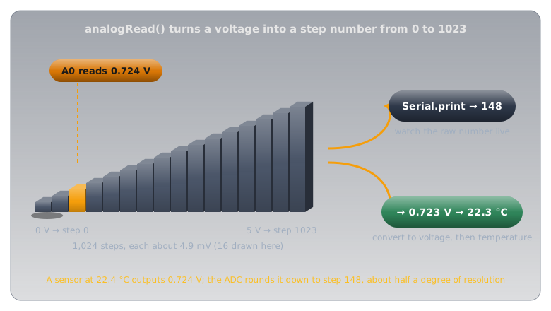
A digital pin's digitalRead() can only ever return two answers. An analog pin (on an Arduino Uno, the pins labelled A0 through A5) measures the actual voltage on the wire and reports, as a number, where it falls between 0V and the supply voltage.
The circuit inside the microcontroller that does the measuring is an analog-to-digital converter (ADC). The Uno's ADC has 10 bits of resolution: it divides the 0–5V range into 1,024 steps of about 4.9 mV and reports which step the voltage falls in, from 0 at 0V to 1023 at the top of the range. That raw number is what analogRead() returns: a position on the 1,024-step scale, not yet a voltage or a temperature.
Why 1,024 and not a rounder number
1,024 is \( 2^{10} \): every value a 10-digit binary number can hold, which is what "10-bit ADC" means. The chip stores each reading as a 10-bit binary number.
What You'll Build🔗
Drawn as a schematic:
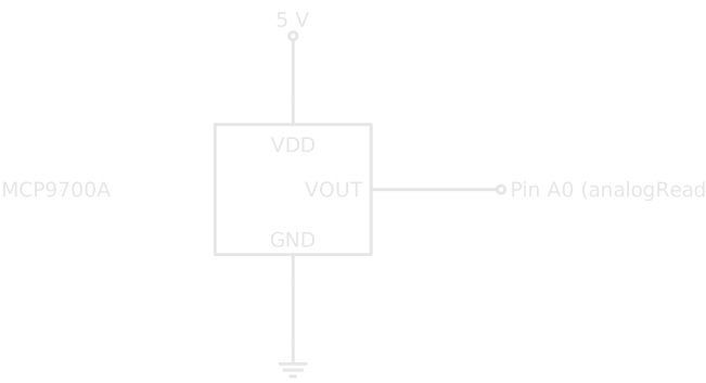
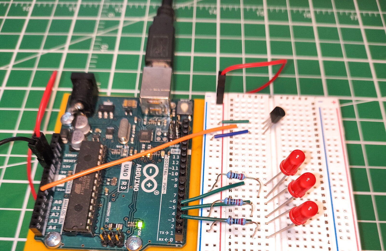
Compared with every LED circuit so far, the current-limiting resistor is missing. Nothing here needs its current limited: the pin is only listening to a voltage the sensor already produces.
Reading and Converting the Value🔗
Two conversions turn the raw ADC number into a temperature: first ADC steps to voltage, then voltage to temperature using the formula from Temperature Sensors.
- Opens a serial connection to your computer at 9600 baud, which is what the Serial Monitor listens to. Serial Communication explains what that number means and what's on the wire.
- Reads the raw ADC value on A0: an integer from
0to1023. - Scales the raw value against the 1,024-step range and the 5V supply to recover the actual voltage.
- Applies the
MCP9700A's formula from Temperature Sensors: subtract the 500 mV offset, then divide by 10 mV/°C, done here as× 100because the voltage is in volts, not millivolts.
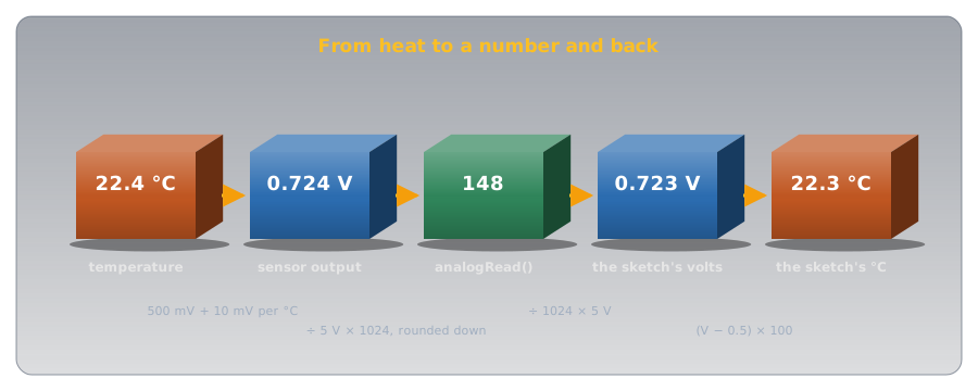
sensorVal is an int because analogRead() always returns a whole number: there's no fractional ADC step. voltage and temperature are float (decimal numbers), because once the arithmetic starts, a fraction of a degree is a real answer.
Verifying It Works🔗
Upload the sketch with arduino-cli, then open the Serial Monitor. You should see a new line roughly every tenth of a second, something close to:
Hold the sensor gently between two fingers. Skin is well above room temperature, so the number should climb within a couple of seconds, and drift back down when you let go. That live response is the point: a physical quantity moving in real time.
Troubleshooting
Raw value stuck at 0: check that VOUT really reaches A0, and that GND connects to the Arduino's ground, not just to the sensor's own leg.
Raw value stuck at 1023: usually VDD and VOUT swapped. Recheck the pinout against Temperature Sensors before applying power again.
Readings jump around wildly: a loose breadboard connection is the most common cause. The MCP9700A's TO-92 body sits proud of the board on three stiff legs, which makes it easy for one leg to seat fully while another barely makes contact; reseat the sensor and press each leg down individually.
Temperature reads plausible but off by a degree or two: that's normal. Revisit the accuracy note in the sensor article; an MCP9700A isn't a precision instrument.
Practice🔗
1. Reading the raw value
Your Serial Monitor shows Raw: 205. What voltage does that correspond to, and what temperature?
Solution
Voltage: \( (205 / 1024.0) \times 5.0 = 1.00\text{V} \). Temperature: \( (1.00 - 0.5) \times 100 = 50°C \). That's hot enough to double-check if you weren't expecting it.
2. Resolution limits
Two consecutive ADC steps are 1 apart — say 147 and 148. How many volts, and how many degrees, does that one-step difference represent?
Solution
One step is \( 5.0 / 1024 \approx 0.0049\text{V} \), about 4.9 mV. At 10 mV per °C, that's roughly 0.49°C per ADC step, the finest change this setup can distinguish.
3. Why an int, not a float
Why does analogRead() return an int, when the voltage it's measuring is a continuous, fractional quantity?
Solution
The ADC has 1,024 discrete steps, and there's no such thing as "step 147.3." The hardware can't report anything finer than one whole step, so the value it returns is always a whole number.
Quick Recap🔗
-
Analog vs. Digital
A digital pin reports HIGH or LOW. An analog pin's ADC measures the actual voltage and reports a position on a 1,024-step scale (0-1023 on the Uno).
-
No Resistor Needed
analogRead()only measures voltage and draws essentially no current, so nothing needs current-limiting the way an LED does. -
Two Conversions
Raw ADC value → voltage (
(value / 1024.0) × 5.0) → temperature (theMCP9700A's formula from Temperature Sensors). -
Resolution Has a Floor
One ADC step ≈ 4.9 mV ≈ half a degree on this sensor. Finer changes than that simply aren't visible to this setup.
What's Next🔗
You can watch the temperature climb in the Serial Monitor, but that means someone has to be looking at a laptop. Building a Threshold Ladder takes this exact circuit and adds three LEDs, so the circuit itself shows when the space has got too warm, with no laptop required.
Further Reading🔗
Official Docs
- analogRead() — Arduino Reference — the full function reference, including notes on reference voltage and conversion time
Related Articles
- Temperature Sensors — why the MCP9700A's output voltage means what it means
- Digital Pins — the HIGH/LOW model this article extends into a continuous range
- arduino-cli — compiling and uploading this sketch