Pull-up and Pull-down Resistors🔗
Beginner
This article follows Digital Pins, where the floating-input problem first appears, and it uses Ohm's Law to size the resistor.
A doorbell button has a spring in it. Let go and it snaps back to a known position: off. Without that spring the button would sit wherever it was last nudged, and the bell would ring or stay silent more or less at random.
A microcontroller's input pin has no spring. Left to itself, it sits at no particular voltage and drifts on the slightest electrical disturbance. A pull-up or pull-down resistor is the spring you add yourself: it gives the pin a definite state to rest at, so the only thing that ever changes its reading is the button or sensor you actually wired up.
This article explains why a bare input misbehaves, the two ways to fix it, how to choose between them, and how to pick the resistor's value.
Why a Bare Input Floats🔗
A pin set to INPUT does one thing: it measures the voltage on it and reports HIGH or LOW. It draws almost no current of its own: it just listens. That sensitivity is the problem.
A wire connected to nothing still behaves like a tiny antenna. It picks up stray electrical fields from the mains wiring in your walls, from nearby jumper wires, even from your hand moving near it. With nothing holding the pin at a real voltage, those faint signals are all it has to report. Read it and you'll get HIGH, then LOW, then HIGH again: a pin that "reads a button" but changes its mind when no one is touching anything. This drifting, undefined state is called floating.
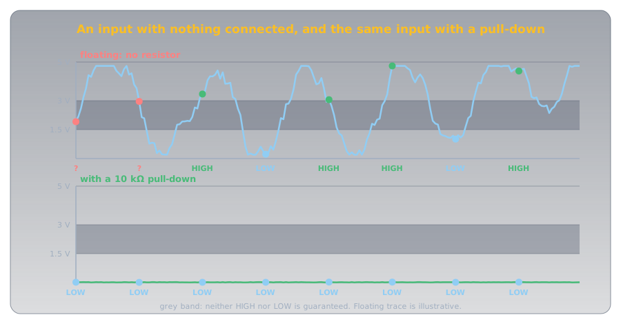
A button by itself doesn't fix this. A button only connects two points while it's pressed. The rest of the time, the pin on the other side of it is connected to nothing, and floats. To read a button reliably, you need something that holds the pin at a known voltage whenever the button isn't doing it. That something is a resistor.
Two Ways to Pin It Down🔗
There are two arrangements, and they are mirror images of each other.
A pull-down resistor connects the pin to ground. Whenever nothing else is driving the pin, the resistor gently "pulls it down" to 0V, so it reads a steady LOW. Press the button, which connects the pin to 5V, and the pin reads HIGH.
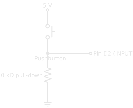
- Button open: only the pull-down connects the pin to anything, so it rests at LOW.
- Button pressed: the button connects the pin to 5V, so it reads HIGH.
The logic reads naturally: pressed means HIGH.
A pull-up resistor connects the pin to the supply voltage instead. Whenever nothing else is driving the pin, the resistor "pulls it up" to 5V, so it reads a steady HIGH. Press the button, wired to connect the pin to ground, and the pin reads LOW.
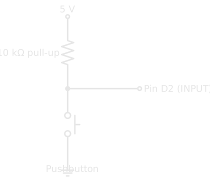
- Button open: only the pull-up connects the pin to anything, so it rests at HIGH.
- Button pressed: the button connects the pin to ground, so it reads LOW.
The logic is inverted: pressed means LOW. That feels backwards at first, but it's the more common arrangement, and the next section explains why.
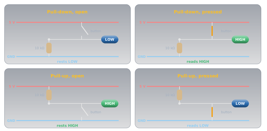
Either way, the pin now has a definite answer at all times. The resistor decides the resting state; the button decides the other state.
Built-In Pull-ups: Often No Resistor Needed🔗
Pull-ups win in practice because microcontrollers have them built into the chip, one per pin, switched on in software. No external resistor, no extra wiring.
On an Arduino you enable it by setting the pin mode to INPUT_PULLUP instead of INPUT:
| Read a button using the built-in pull-up | |
|---|---|
That single word connects a resistor of 20 to 50 kΩ between the pin and 5V inside the chip (the range the ATmega328P datasheet gives). The button just connects the pin to ground. It's the simplest reliable way to read a button, which is why it's everywhere.
The Uno has pull-ups only
The Uno's ATmega328P has internal pull-ups but no internal pull-downs, so on an Uno a pull-down is always an external resistor. Newer chips such as the ESP32 and the Raspberry Pi Pico's RP2040 offer both, selected with INPUT_PULLDOWN. The pull-up habit dates from chips like the Uno's, and it stuck because it works everywhere.
Sizing the Resistor🔗
A pull resistor's value is a balance, and Ohm's Law sets both ends of it.
When the button is pressed, the resistor has the full supply voltage across it, so it passes a small current straight from 5V to ground for as long as you hold the button. From \( I = V / R \):
- Too small (say 100 Ω): \( 5\text{V} / 100\ \Omega = 50\text{ mA} \) wasted continuously while pressed. That's more than an LED draws, and at 0.25 W it's the full rating of a typical ¼ W resistor, all turned into heat for nothing.
- Too large (say 10 MΩ): the pull is so weak that noise can overpower it, and the pin starts to float again, the very problem you were solving.
- Just right (10 kΩ): \( 5\text{V} / 10\,000\ \Omega = 0.5\text{ mA} \), negligible waste, yet a firm enough grip to hold the pin steady.
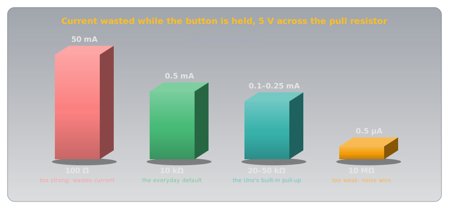
That's why 10 kΩ is the everyday default for a pull-up or pull-down on a button. It's strong enough to win against noise and weak enough that the current it wastes doesn't matter.
Where You'll Meet Them Again🔗
The same idea, giving a line a defined resting voltage, shows up all over electronics:
- Buttons and switches: the case in this article.
- Communication lines: protocols like I²C require pull-up resistors on their shared wires, so every device sees a clean HIGH when no one is talking.
- Reset and enable pins: many chips need a pull-up or pull-down to sit in a known state at power-on instead of doing something random.
Learn the pattern on a button and a datasheet's "add a 4.7 kΩ pull-up" stops being mysterious.
Practice🔗
1. Pressed means HIGH
You want a circuit where the input pin reads LOW at rest and HIGH when the button is pressed. Which resistor arrangement is that, and how is the button wired?
Solution
That's a pull-down. The resistor ties the pin to ground, so it rests LOW. The button is wired to connect the pin to 5V, so pressing it drives the pin HIGH. (If you'd instead used a pull-up, the logic would be inverted: rest HIGH, pressed LOW.)
2. The warm resistor
A beginner uses a 220 Ω resistor as a pull-down because it's what they had on hand. The circuit works, but they notice the resistor gets warm whenever the button is held. What's happening, and what should they use?
Solution
While the button is held, the 220 Ω resistor carries the full supply across it: \( 5\text{V} / 220\ \Omega \approx 23\text{ mA} \), dissipated as heat for as long as the button is down. It works, but it wastes current and warms the part. A 10 kΩ resistor does the same job while passing only about 0.5 mA: strong enough to hold the pin, gentle enough to stay cool.
3. No resistor at all
On a different board you read a button with pinMode(2, INPUT_PULLUP) and no external resistor anywhere — yet the pin reads reliably. How?
Solution
INPUT_PULLUP switches on a pull-up resistor built into the microcontroller, connected internally between the pin and the supply. It does the same job as an external pull-up, so the pin rests HIGH and reads LOW when the button connects it to ground, with no external part.
Quick Recap🔗
-
The Problem
A bare input pin floats: it drifts on electrical noise and reads unpredictably. A button alone doesn't help, because it only connects the pin while pressed.
-
The Fix
A pull-down ties the pin to ground (rests LOW); a pull-up ties it to the supply (rests HIGH). The resistor sets the resting state; the button sets the other.
-
The Easy Way
Microcontrollers have built-in pull-ups, enabled with
pinMode(pin, INPUT_PULLUP), so a button to ground needs no external resistor. -
The Value
10 kΩ is the everyday default: small enough current to ignore (≈ 0.5 mA), firm enough to beat the noise. Too small wastes power; too large floats again.
What's Next🔗
You can now read an input as reliably as you can drive an output. Digital pins only answer HIGH or LOW, though, and plenty of the world isn't on or off. Reading an Analog Sensor measures the voltage in between, using a temperature sensor whose output rises steadily with the heat.
To run any of this, arduino-cli compiles and uploads the sketches to your board.
Further Reading🔗
Fundamentals
- Pull-up Resistors — SparkFun — the same idea with the Ohm's Law sizing worked through in more detail
Related Articles
- Digital Pins — INPUT and OUTPUT, and where the floating problem first appears
- Ohm's Law and Power — the law behind choosing a resistor value
- Resistor Color Codes — decode the 10 kΩ pull resistor from this article by its bands
- Series and Parallel Circuits — current-limiting resistors, the other everyday job a resistor does